NUMERICAL APPROACH TO FIND OUT EFFECTIVE AREA AND BASE PRESSURE BELOW FOUNDATIONS SUBJECTED TO LARGE BIAXIAL MOMENTS
It is never been so easy to find out the effective area under the foundations subjected to large moments. Effective area below the foundation with only axial moment can be found out with help of simple banding theory. In actual engineering problems we rarely face the case of foundations which are truly concentrically loaded or with only uniaxial moment. Analysis of foundation subjected large biaxial moments can be done with numerical methods. Most of the engineers use K value mentioned in Teng’s chart presented by Wayne C. Teng in his book “Foundation Design” to find out the maximum pressure.
In this article we are going to discuss about the numerical method described by Ralph B. Peck in his book “Foundation Engineering”. This method is well suited for development of computer program.
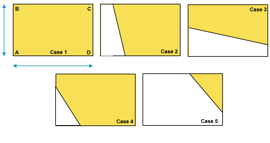
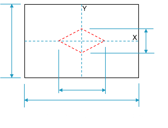
Generally, there are five cases of foundation loading occur (See Fig-1). Out of five cases, Case 1 represents the condition where the loads acting with a small eccentricity. The eccentricity in this case lies in the kern zone (marked by red dotted lines in Fig-2 below). This kern zone is defined in the middle third of the base area. In Case 1 scenario the neutral axis falls outside the base area and whole area is in contact with soil underneath. Calculation of base pressure is simple in this case. Pressure intensity at different locations can be found out by equation given below:

Where, p is intensity of pressure at a distance x and y from centroid of the base along x and y direction. (x and y can be +ve or –ve with respect to centroid of the base). P is vertically downward load, Xe and Ye are the eccentricities along x and y direction respectively.


For Case 1, eccentricities Xe = My/P and Ye= Mx/P lies in the kern zone leading to whole area of the base effective and in contact with soil underneath.
In all other cases from Case 2 to Case 5, eccentricity lies outside the kern zone due to high biaxial moments. In all these cases neutral axis falls inside the base area, produce tension and compression under the base. Here in these cases tension is produced under the base means portion of the base area loses its contact with soil causing uplift of more than one corners depending on the intensities of biaxial moments acting on it.
For Case 1, there is no uplift. In Case 2, left two corners are lifted up. In Case 3, bottom left and right corners are lifted up. In Case 4 only one corner (bottom left) is uplifted. In Case 5, base is seem to be subjected to very large moments and except upper right corner, all corners are lifted up.
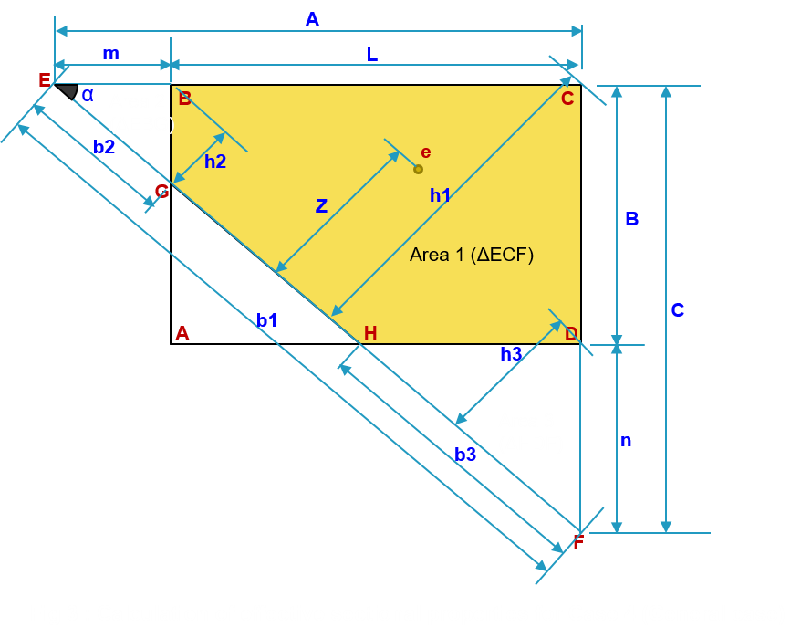
In our daily engineering problems we face cases other than Case 1 frequently. The equation mentioned above to calculate pressures will not hold correct in these cases; because the effective area is not considered in this equation. To analyse such problems following algorithm to be followed along with case 4 as general case and Fig-2:
- Convert the eccentricities in positive quadrant for generalizing the cases.
- Find out which corners of the footing are subjected to tension with the help of equation mentioned above
- Find out the location of trial neutral axis (GH) with the help of pressure intensities at the corners.
- Find out the area, moment of inertia about NA of base under compression and distance of eccentricity from this trial NA
- Find out revised pressures at the corners and volume of pressure envelop and its CG
- Compare the volume of pressure envelop with applied load P and CG of volume with eccentricity
- Alter the position of NA in such way that the error in volume and CG converges to minimum
In Table-1, list of required formulas is mentioned.

| Table-1: Formula | |
| Angle between A & C | alpha = Atn(C / A) |
| m and n | If A > L then m = A – L else m = 0
If C > B then n = C –B else n = 0 |
| c1=B + Tan(alpha)*(L-A) | |
| Distance of CG of loads from EF | Z = Abs((-Tan(alpha) * (Xe + L / 2) - (Ye + B / 2) + c1)) / ((-Tan(alpha)) ^ 2 + 1) ^ 0.5 |
| Area calculation: | |
| Area of Δ ECF | a1 = 0.5 * A * C |
| Base length of Δ ECF | b1 = (A ^ 2 + C ^ 2) ^ 0.5 |
| Height of Δ ECF | h1 = A * Sin(alpha) |
| MI of Δ ECF about EF | Igh1 = 1 / 12 * b1 * h1 ^ 3 |
| Area of Δ ECF | a2 = 0.5 * m * m * Tan(alpha) |
| Base length of Δ EBG | b2 = (m ^ 2 + (m * Tan(alpha)) ^ 2) ^ 0.5 |
| Height of Δ EBG | h2 = m * Sin(alpha) |
| MI of Δ EBG about EF | Igh2 = 1 / 12 * b2 * h2 ^ 3 |
| Area of Δ HDF | a3 = 0.5 * n * n / Tan(alpha) |
| Base length of Δ HDF | b3 = (n ^ 2 + (n / Tan(alpha)) ^ 2) ^ 0.5 |
| Height of Δ HDF | h3 = n * Cos(alpha) |
| MI of Δ HDF about EF | Igh3 = 1 / 12 * b3 * h3 ^ 3 |
| Effective area | Aeff = a1 - a2 - a3 |
| Effective moment of inertia | Igh = Igh1 - Igh2 - Igh3 |
| Revised pressure at corners of the base: | |
| Pressure intensity at corner A | Pa = 0 |
| Pressure intensity at corner B | Pb = P * Z * h2 / Igh |
| Pressure intensity at corner C | Pc = P * Z * h1 / Igh |
| Pressure intensity at corner D | Pd = P * Z * h3 / Igh |
| Pressure volume calculation: | |
| Volume of pyramid 1 | v1 = 1 / 3 * a1 * Pc |
| CG of volume 1 from AB | gx1 = L - A / 4 |
| CG of volume 1 from AD | gy1 = B - C / 4 |
| Volume of pyramid 2 | v2 = 1 / 3 * a2 * Pb |
| CG of volume 2 from AB | gx2 = -m / 4 |
| CG of volume 2 from AD | gy2 = B - m * Tan(alpha) / 4 |
| Volume of pyramid 3 | v3 = 1 / 3 * a3 * Pd |
| CG of volume 3 from AB | gx3 = L - (n / Tan(alpha)) / 4 |
| CG of volume 3 from AD | gy3 = -n / 4 |
| Effective pressure volume | v = v1 - v2 - v3 |
| Resultant CG from AB | Gx = (v1 * gx1 - v2 * gx2 - v3 * gx3) / v |
| Resultant CG from AD | Gy = (v1 * gy1 - v2 * gy2 - v3 * gy3) / v |
Iteration process
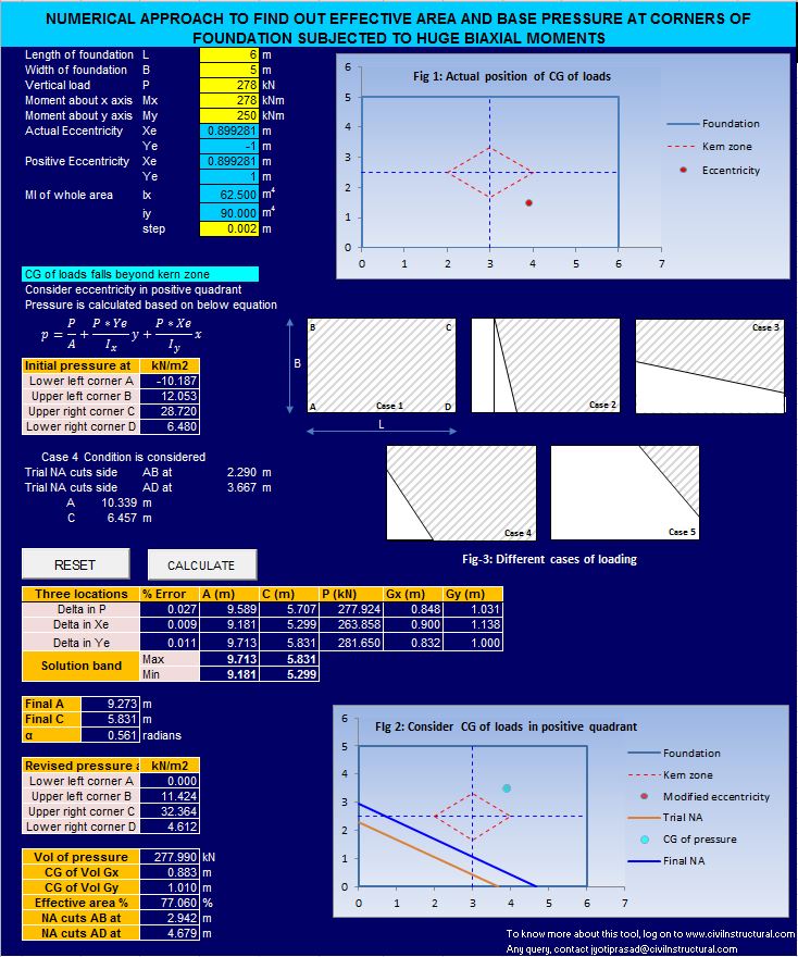
In first set of iterations, with the help of above formulae, effective pressure volume and CG compared with applied load and eccentricity respectively. With small step A and C are altered in such a way that three locations for desired accuracy in P, Xe and Ye are achieved.
Now the solution lies in the band formed by these three sets of values of A & C. as shown in Fig : 4.
Find out the position of neutral axis within the solution band mentioned above where all the three parameters i.e. P, Xe and Ye converge to exact solution. In the second set of iterations, with a significant step, mathematically NA to be shifted by considering E1 & F1 as pivotal point each time. In first step, keep E1 fixed and alter distance C from F1 to F2 and in second step, keep F1 fixed and alter distance A from E1 to E2. Results for all such locations saved and one set of value of A & C is found out where error in P, Xe and Ye are minimum all together.

References:
- “Foundation design” by Wayne C Teng
- “Foundation engineering” by Ralph B. Peck, Walter E. Hanson, Thomas H. Thornburn
- Journal of bridge engineering “Bearing Pressure for rectangular footings with biaxial uplift” by Kenneth E. Wilson
- Literature “Analysis of eccentrically loaded rectangular footing resting on soil- A numerical approach” by Jignesh V Chokshi
- Literature “How to calculate footing soil bearing by computer” by Eli Czerniak
To download ready to use Soft Tool, click here….
To learn the code, watch the video…..
If you like the article, share with your friends and colleagues…
Drop your comments if any on my contact page….
